|
||||||||||||
|
|
|
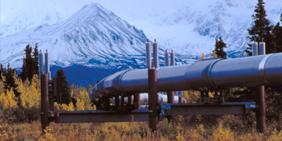
Trans-Alaska Pipeline
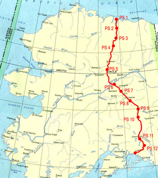
The 800-mile-long Trans Alaska Pipeline System (TAPS) is one of the largest pipeline systems in the world. It stretches from Prudhoe Bay on Alaska’s North Slope, through rugged and beautiful terrain, to Valdez, the northernmost ice-free port in North America. All of the oil is transported to refineries in the United States.
The concept of transporting oil south from Alaska was discussed as early as the 1960s. In 1968, large crude oil reserves were discovered at Prudhoe Bay by the Atlantic Richfield Company (ARCO). ARCO joined with BP Oil and Humble Oil to form the Trans-Alaska Pipeline Systems (TAPS). TAPS was proposed to ship crude oil to the southern Alaska seaport of Valdez (an ice-free port), from where it would be shipped to refineries by tanker. Pipeline construction from Prudhoe Bay required transiting a route where much of the right-of-way was on federal and state lands. Legislation (the Trans-Alaska Pipeline Authorization Act [P.L. 93-153]) was required to end what had become a stalemate over the route. This right-of-way legislation enabled the pipeline to be constructed. Environmental studies for the pipeline were started and applications for permits submitted in 1968. Suits were filed by environmental groups and others to block pipeline construction in 1970. Several Native villages filed a lawsuit claiming the pipeline would cross their land. The land ownership question was settled with Congressional passage of the Alaska Native Land Claims Settlement Act and its signature into law by President Richard Nixon in December 1971.
The 48-inch special cold-weather steel was ordered from Japan in April 1969. The building permit for the pipeline was issued in 1974.
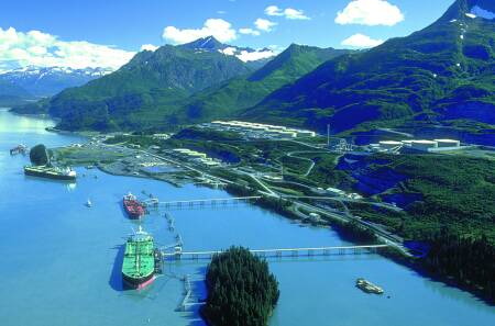
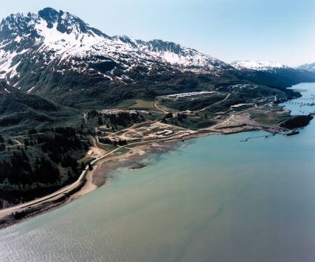
Valdez Marine Terminal The pipeline route would cover 800 miles from Prudhoe Bay to the port of Valdez, the northernmost ice-free port in the United States. Actual construction began in April 1974 and was completed in June 1977 at a cost of approximately $8 billion. At the time, it was the largest privately funded construction project in history. Approximately 2,000 contractors and subcontractors, as well as approximately 70,000 workers, were employed to work on the project.
Paralleling the pipeline from Livengood to Deadhorse, the Dalton Highway (locally known as the Haul Road) was built as a supply route for use in construction, operation, and maintenance of the northern portion of TAPS and the oil fields on the North Slope. This road is now a State highway.
Valdez Marine Terminal
The Alyeska Pipeline Service Company, named after the Aleut word Alyeska meaning mainland, was established in 1970 and charged with designing, constructing, operating, and maintaining the Trans Alaska Pipeline System, commonly called TAPS. Key events in the history of the Trans-Alaska Pipeline System
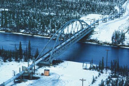
Gulkana River tiered-arch bridge
The consortium of companies that own TAPS today includes:
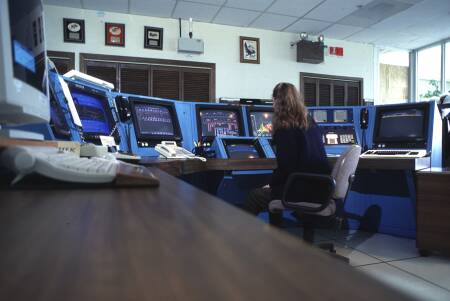
Pipeline Operations
Operators at the Valdez Operations Control Center monitor the performance of pipeline operations
Pipeline Engineering
Cost Approximately $8
billion for construction of entire system, including Terminal and pump stations,
at conclusion of initial construction period in 1977. Does not include interest
on capital investment, or capital construction after 1977.
Concrete weights
Mainline crossings
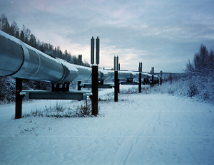
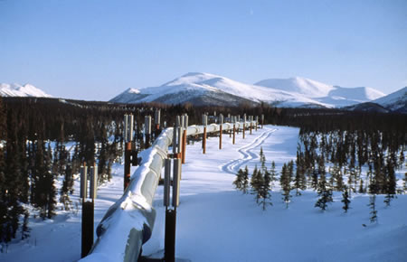
Design modes Selection — Soil sampling and other means were used to determine soil types along the route. Where thaw-stable soils were found, the pipeline was buried in the conventional manner. In areas of thaw-unstable soils, and where heat from the oil in the pipeline might cause thawing and consequent loss of soil foundation stability, the pipeline was insulated and elevated above ground by means of a unique support system. Basic types and miles of each —
Description —
Pipeline buried in the standard method lies on a layer of bedding material (well drained sandy gravel without sharp rocks) covered with prepared gravel padding and soil fill material. Insulation
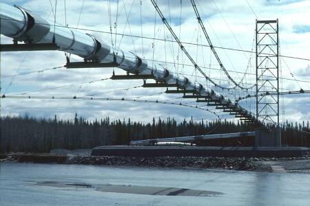
Tanana River suspension bridge Gabion & concrete mats Used in Atigun Floodplain Pipe Replacement Project for scour protection of the new pipe because less cover on top of new pipe.
Land Ownership Ownership, entire system, by area:
Ownership, pipeline only, length
Pipeline in municipal jurisdiction, approx.
Linefill Definition - Amount of oil in pipeline from PS 1 to Marine terminal. The linefill is 9,059,057 bbl.
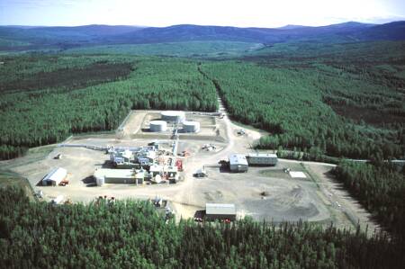
Pump Station 1 receives and meters oil from the producers Permanent facilities Access roads, dimensions — 120 ft. to 7.5 mi. long; 28 ft. wide, minimum 3 ft. gravel base. Access roads, number — 225, linking state roads with pipeline, pump stations and airfields. Airfields, land status and length —
Pressure Relief Station — 1 (PS 5, reinjects oil drained down for pressure relief, but does not have mainline pumps and does not boost total stream). Marine terminal — 1 (Valdez). Pig launching/receiving facilities — 3 (PS 1, 4, and Marine Terminal). Pipe shoes, number — 39,000 approx. Pump stations, operating — 11 (10 pump stations, 1 relief station) Topping units — 3 (PS 6, 8, and 10. PS 8 and 10 topping units placed in standby, summer 1996. PS6 topping unit placed in standby summer 1997.) Pipeline Valves, types and number —
Pump Station 7 is about 1.3 miles southeast of the Tatalina River in a wooded area. PS 7 is similar to PS 2 with two mainline pumps instead of three. Thermal expansion Definitions - Thermal expansion - change in pipe length due to change in crude oil temperature Tie-in temperature - actual pipe temperatures at the time when final welds were made which joined strings of pipe into a continuous line Hot position - pipe at maximum oil temperature (145° F) Cold position - pipe at minimum
steel temperature Each 40 ft. length of pipe expands .031 inches with each 10° F rise in temperature and contracts the same distance with each 10°F drop in temperature. Longitudinal expansion of typical 720 ft. straight above-ground segment from min. tie-in temperature to maximum operating temperature - 9 inches. Note: due to anchoring, the pipeline does not expand lengthwise but shifts laterally on the above-ground supports (See zig zag configuration , below) Maximum above-ground lateral movement-
Thermal stress - maximum, 25,000
psi - where below ground pipeline is fully restrained by the soil, the maximum
longitudinal stress due to change in temperature from pipe temperature at tie-in
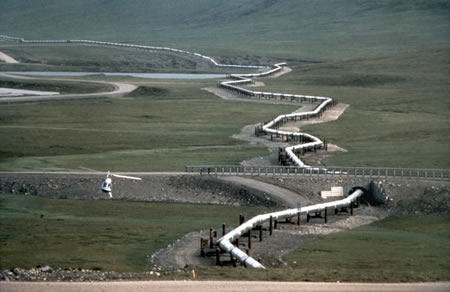
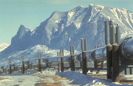
to maximum oil temperature Zig zag Configuration Above-ground sections of the
pipeline are built in a zig zag configuration to allow for expansion or
contraction of the pipe because of temperature changes. The design also allows
for pipeline movement caused by an earthquake. Refrigerated Burial of Pipe
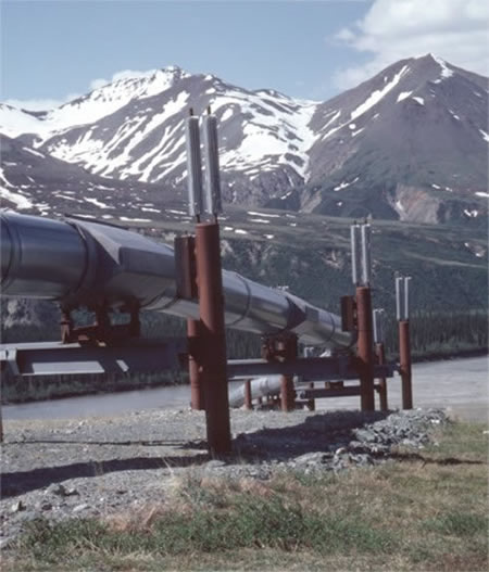
VSMs (Vertical Support Members) Basic data —
Depth at which embedded — 15 ft. to 70 ft. Distance between —
Heat pipes, number fitted with — 61,000 (122,000 individual heat pipes, 2 per VSM, where fitted)
credit: Alyeska Pipeline Service Company, State of Alaska, U.S. Department of the Interior Bureau of Land Management |