|
Natural Gas
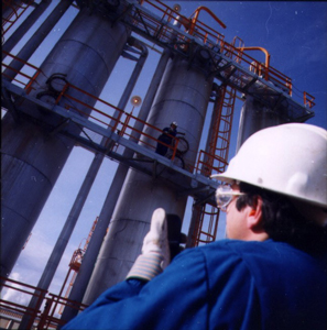
Natural gas, in itself, might be considered an uninteresting gas - it is
colorless, shapeless, and odorless in its pure form.
Natural gas is the gas
component of coal and oil formation. It is used in industrial and
commercial heating and cooking, and, increasingly, to fuel electricity
generation. In a compressed form, natural gas can also be used as a
transportation fuel. Natural gas is either found mixed in oil or is
released from coal. Energy in 6,000 cubic feet of natural gas is
equivalent to one barrel of oil.
Wells for natural gas
are drilled in underground reservoirs of porous rock. When it is
removed from a reservoir, natural gas can either be pumped to the
processing station for removal of liquid hydrocarbons, sulfur,
carbon dioxide, and other components, or stored in large caverns
underground until it is needed. Pipelines are the main method of
transporting natural gas. Natural gas can also be liquefied and
shipped overseas, but this process is complex and expensive.
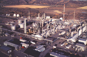
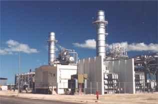
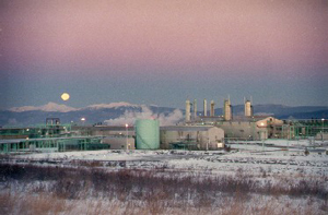
Electrical generation
by natural gas has been improved by the development of
combined-cycle systems. These systems put together a
natural-gas-fueled combustion turbine with a heat-recovery steam
generator and steam turbine, to produce electricity in two ways
rather than just one. The result: roughly 60 percent of the heat
from the natural gas is harnessed to make electricity, creating a
more energy-efficient system.
Natural gas was formed millions of
years ago when most of the earth was covered by water. Plant and tiny animal
remains were mixed and layered with sand and mud. When the Earth underwent
natural but drastic changes to form today’s landscape, the intense heat and
pressure transformed these fossils into hydrocarbons—chemical compounds of
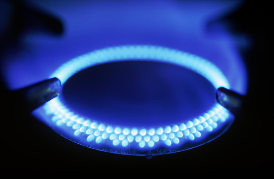
hydrogen and carbon atoms. Natural gas is made up mainly of a chemical called
methane, a simple, compound that has a carbon atom surrounded by four hydrogen
atoms. Methane is highly flammable and burns almost completely. There is no ash
and very little air pollution. Depending on the arrangement of the atoms, what
were once sea plants and animals are now natural gas or crude oil deposits
contained in the earth’s crust. Natural gas (a combustible, gaseous mixture of
simple hydrocarbons) is a very light portion of petroleum, which includes both
natural gas and crude oil. Natural gas may rise to the surface through natural
openings in the earth’s crust or can be brought to the surface through man-made
wells. Humans discovered thousands of years ago that this naturally occurring
resource could be burned and used for heat and light.
|
|
|
Natural gas is nothing
new. In fact, most of the natural gas that is brought out
from under the ground is millions and millions of years old.
However, it was not until recently that methods for
obtaining this gas, bringing it to the surface, and putting
it to use were developed.
Before there was an
understanding of what natural gas was, it posed somewhat of
a mystery to man. Sometimes, such things as lightning
strikes would ignite natural gas that was escaping from
under the earth's crust. This would create a fire coming
from the earth, burning the natural gas as it seeped out
from underground. These fires puzzled most early
civilizations, and were the root of much myth and
superstition. One of the most famous of these types of
flames was found in ancient Greece, on Mount Parnassus
approximately 1000 B.C. A goat herdsman came across what
looked like a 'burning spring', a flame rising from a
fissure in the rock. The Greeks, believing it to be of
divine origin, built a temple on the flame. This temple
housed a priestess who was known as the Oracle of Delphi,
giving out prophecies she claimed were inspired by the
flame.
 |
|
The Oracle at Delphi, Greece |
|
Source: Pascal Troxler |
These types of springs
became prominent in the religions of India, Greece, and
Persia. Unable to explain where these fires came from, they
were often regarded as divine, or supernatural. It wasn't
until about 500 B.C. that the Chinese discovered the
potential to use these fires to their advantage. Finding
places where gas was seeping to the surface, the Chinese
formed crude pipelines out of bamboo shoots to transport the
gas, where it was used to boil sea water, separating the
salt and making it drinkable.
Britain was the first
country to commercialize the use of natural gas. Around
1785, natural gas produced from coal was used to light
houses, as well as streetlights.
 |
|
A Natural Gas Streetlight |
|
Source: DOE |
Manufactured natural
gas of this type (as opposed to naturally occurring gas) was
first brought to the United States in 1816, when it was used
to light the streets of Baltimore, Maryland. However, this
manufactured gas was much less efficient, and less
environmentally friendly, than modern natural gas that comes
from underground.
Naturally occurring
natural gas was discovered and identified in America as
early as 1626, when French explorers discovered natives
igniting gases that were seeping into and around Lake Erie.
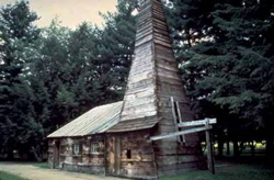
The American natural gas industry got its beginnings in this
area. In 1859, Colonel Edwin Drake (a former railroad
conductor who adopted the title 'Colonel' to impress the
townspeople) dug the first well. Drake hit oil and natural
gas at 69 feet below the surface of the earth.
 |
|
A Reconstruction of 'Colonel' Drake's First Well in
Titusville, Pa |
|
Source: API |
Most in the industry
characterize this well as the beginning of the natural gas
industry in America. A two-inch diameter pipeline was built,
running 5 and ½ miles from the well to the village of
Titusville, Pennsylvania. The construction of this pipeline
proved that natural gas could be brought safely and
relatively easily from its underground source to be used for
practical purposes.
In 1821, the first
well specifically intended to obtain natural gas was dug in
Fredonia, New York by William Hart. After noticing gas
bubbles rising to the surface of a creek, Hart dug a 27-foot
well to try and obtain a larger flow of gas to the surface.
Hart is regarded by many as the 'father of natural gas' in
America. Expanding on Hart's work, the Fredonia Gas Light
Company was eventually formed, becoming being the first
American natural gas company.
During most of the
19th century, natural gas was used almost exclusively as a
source of light. Without a pipeline infrastructure, it was
difficult to transport the gas very far, or into homes to be
used for heating or cooking. Most of the natural gas
produced in this era was manufactured from coal, as opposed
to transported from a well. Near the end of the 19th
century, with the rise of electricity, natural gas lights
were converted to electric lights. This led producers of
natural gas to look for new uses for their product.
In 1885, Robert Bunsen
invented what is now known as the Bunsen burner. He managed
to create a device that mixed natural gas with air in the
right proportions, creating a flame that could be safely
used for cooking and heating. The invention of the Bunsen
burner opened up new opportunities for the use of natural
gas in America, and throughout the world. The invention of
temperature-regulating thermostatic devices allowed for
better use of the heating potential of natural gas, allowing
the temperature of the flame to be adjusted and monitored.
 |
|
A Typical Bunsen Burner |
|
Source: DOE |
Without any way to
transport it effectively, natural gas discovered pre-WWII
was usually just allowed to vent into the atmosphere, or
burnt, when found alongside coal and oil, or simply left in
the ground when found alone.
One of the first
lengthy pipelines was constructed in 1891. This pipeline was
120 miles long, and carried natural gas from wells in
central Indiana to the city of Chicago. However, this early
pipeline was very rudimentary, and was not very efficient at
transporting natural gas. It wasn't until the 1920s that any
significant effort was put into building a pipeline
infrastructure. After World War II, welding techniques, pipe
rolling, and metallurgical advances allowed for the
construction of reliable pipelines. This post-war pipeline
construction boom lasted well into the ‘60s, and allowed for
the construction of thousands of miles of pipeline in
America.
Once the
transportation of natural gas was possible, new uses for
natural gas were discovered. These included using natural
gas to heat homes and operate appliances such as water
heaters and oven ranges. Industry began to use natural gas
in manufacturing and processing plants. Also, natural gas
was used to heat boilers used to generate electricity. The
transportation infrastructure had made natural gas easy to
obtain, and it was becoming an increasingly popular form of
energy.
|
|
What is Natural Gas?
In its natural state you can’t see
or smell natural gas. It is colorless, odorless and lighter than air.
Mercaptan, a chemical odorant, is added to natural gas so it can be smelled if
it leaks.
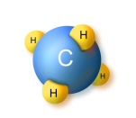
Natural gas is made up mostly of
methane, which has a simple hydrocarbon structure of one carbon atom and four
hydrogen atoms (CH4). This means it burns easily and emits less pollution. When
natural gas is burned, it produces mostly carbon dioxide and water vapor. While
natural gas is formed primarily of methane, it can also include ethane,
propane, butane and pentane.
Natural gas can be found in a
variety of different underground formations, including: shale formations,
sandstone beds, coal seams, and deep, salt water aquifers (underground ponds of
water).
Natural gas wells have
traditionally been drilled vertically, at depths ranging from a few thousand
feet to as deep as five miles.
Natural gas can be found in
a variety of different underground formations, including:
-
shale formations
-
sandstone beds
-
coal seams
The Formation of
Natural Gas
Natural gas is a fossil
fuel. Like oil and coal, this means that it is, essentially, the remains
of plants and animals and microorganisms that lived millions and millions
of years ago. But how do these once living organisms become an inanimate
mixture of gases?
There are many different
theories as to the origins of fossil fuels. The most widely accepted
theory says that fossil fuels are formed when organic matter (such as the
remains of a plant or animal) is compressed under the earth, at very high
pressure for a very long time. This is referred to as thermogenic methane.
Similar to the formation of oil, thermogenic methane is formed from
organic particles that are covered in mud and other sediment. Over time,
more and more sediment and mud and other debris are piled on top of the
organic matter. This sediment and debris puts a great deal of pressure on
the organic matter, which compresses it. This compression, combined with
high temperatures found deep underneath the earth, breaks down the carbon
bonds in the organic matter. As one gets deeper and deeper under the
earth’s crust, the temperature gets higher and higher. At low temperatures
(shallower deposits), more oil is produced relative to natural gas. At
higher temperatures, however, more natural gas is created, as opposed to
oil. That is why natural gas is usually associated with oil in deposits
that are 1 to 2 miles below the earth's crust. Deeper deposits, very far
underground, usually contain primarily natural gas, and in many cases,
pure methane.
Natural gas can also be
formed through the transformation of organic matter by tiny
microorganisms. This type of methane is referred to as biogenic methane.
Methanogens, tiny methane-producing microorganisms, chemically break down
organic matter to produce methane. These microorganisms are commonly found
in areas near the surface of the earth that are void of oxygen. These
microorganisms also live in the intestines of most animals, including
humans. Formation of methane in this manner usually takes place close to
the surface of the earth, and the methane produced is usually lost into
the atmosphere. In certain circumstances, however, this methane can be
trapped underground, recoverable as natural gas. An example of biogenic
methane is landfill gas. Waste-containing landfills produce a relatively
large amount of natural gas from the decomposition of the waste materials
that they contain. New technologies are allowing this gas to be harvested
and used to add to the supply of natural gas.
A third way in which
methane (and natural gas) may be formed is through abiogenic processes.
Extremely deep under the earth's crust, there exist hydrogen-rich gases
and carbon molecules. As these gases gradually rise towards the surface of
the earth, they may interact with minerals that also exist underground, in
the absence of oxygen. This interaction may result in a reaction, forming
elements and compounds that are found in the atmosphere (including
nitrogen, oxygen, carbon dioxide, argon, and water). If these gases are
under very high pressure as they move toward the surface of the earth,
they are likely to form methane deposits, similar to thermogenic methane.
Exploration
The practice of locating
natural gas and petroleum deposits has been transformed dramatically in
the last 20 years with the advent of extremely advanced, ingenious
technology. In the early days of the industry, the only way of locating
underground petroleum and natural gas deposits was to search for surface
evidence of these underground formations. Those searching for natural gas
deposits were forced to scour the earth, looking for seepages of oil or
gas emitted from underground before they had any clue that there were
deposits underneath. However, because such a low proportion of petroleum
and natural gas deposits actually seep to the surface, this made for a
very inefficient and difficult exploration process. As the demand for
fossil fuel energy has increased dramatically over the past years, so has
the necessity for more accurate methods of locating these deposits.
Sources of Data
Technology has allowed for
a remarkable increase in the success rate of locating natural gas
reservoirs. In this section, it will be outlined how geologists and
geophysicists use technology and knowledge of the properties of
underground natural gas deposits to gather data that can later be
interpreted and used to make educated guesses as to where natural gas
deposits exist. However, it must be remembered that the process of
exploring for natural gas and petroleum deposits is characteristically an
uncertain one, due to the complexity of searching for something that is
often thousands of feet below ground.
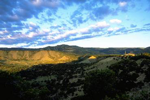
Geological Surveys
Exploration for natural gas
typically begins with geologists examining the surface structure of the
earth, and determining areas where it is geologically likely that
petroleum or gas deposits might exist. It was discovered in the mid 1800s
that ‘anticlinal slopes’ had a particularly increased chance of containing
petroleum or gas deposits. These anticlinal slopes are areas where the
earth has folded up on itself, forming the dome shape that is
characteristic of a great number of reservoirs. By surveying and mapping
the surface and sub-surface characteristics of a certain area, the
geologist can extrapolate which areas are most likely to contain a
petroleum or natural gas reservoir. The geologist has many tools at his
disposal to do so, from the outcroppings of rocks on the surface or in
valleys and gorges, to the geologic information attained from the rock
cuttings and samples obtained from the digging of irrigation ditches,
water wells, and other oil and gas wells. This information is all combined
to allow the geologist to make inferences as to the fluid content,
porosity, permeability, age, and formation sequence of the rocks
underneath the surface of a particular area. For example, in the picture
shown, a geologist may study the outcroppings of rock to gain insight into
the geology of the subsurface areas.
 |
|
Surface Geology |
|
Source: Anadarko Petroleum Corporation |
Once the geologist has
determined an area where it is geologically possible for a natural gas or
petroleum formation to exist, further tests can be performed to gain more
detailed data about the potential reservoir area. These tests allow for
the more accurate mapping of underground formations, most notably those
formations that are commonly associated with natural gas and petroleum
reservoirs. These tests are commonly performed by a geophysicist, one who
uses technology to find and map underground rock formations.
Seismic Exploration
Arguably the biggest
breakthrough in petroleum and natural gas exploration came through the use
of basic seismology. Seismology refers to the study of how energy, in the
form of seismic waves, moves through the Earth's crust and interacts
differently with various types of underground formations. In 1855, L.
Palmiere developed the first 'seismograph', an instrument used to detect
and record earthquakes. This device was able to pick up and record the
vibrations of the earth that occur during an earthquake. However, it
wasn't until 1921 that this technology was applied to the petroleum
industry and used to help locate underground fossil fuel formations.
 |
|
Placing Geophones |
|
Source: API |
The basic concept of
seismology is quite simple. As the Earth's crust is composed of different
layers, each with its own properties, energy (in the form of seismic
waves) traveling underground interacts differently with each of these
layers. These seismic waves, emitted from a source, will travel through
the earth, but also be reflected back toward the source by the different
underground layers. Through seismology, geophysicists are able to
artificially create vibrations on the surface and record how these
vibrations are reflected back to the surface, revealing the properties of
the geology beneath.
An analogy that makes
intuitive sense is that of bouncing a rubber ball. A rubber ball that is
dropped on concrete will bounce in a much different way than a rubber ball
dropped on sand. In the same manner, seismic waves sent underground will
reflect off dense layers of rock much differently than extremely porous
layers of rock, allowing the geologist to infer from seismic data exactly
what layers exist underground and at what depth. While the actual use of
seismology in practice is quite a bit more complicated and technical, this
basic concept still holds.
 |
|
Seismology in Practice |
|
Source: API |
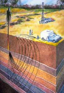
Onshore Seismology
In practice, using
seismology for exploring onshore areas involves artificially creating
seismic waves, the reflection of which are then picked up by sensitive
pieces of equipment called 'geophones' that are embedded in the ground.
The data picked up by these geophones is then transmitted to a seismic
recording truck, which records the data for further interpretation by
geophysicists and petroleum reservoir engineers. The drawing shows the
basic components of a seismic crew. The source of seismic waves (in this
case an underground explosion) creates that reflect off the different
layers of the Earth, to be picked up by geophones on the surface and
relayed to a seismic recording truck to be interpreted and logged.
Although the seismograph was originally developed to measure earthquakes,
it was discovered that much the same sort of vibrations and seismic waves
could be produced artificially and used to map underground geologic
formations. In the early days of seismic exploration, seismic waves were
 |
| A
Seismic Vibrator Truck |
|
Source: Natural Resources Canada |
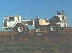
created using dynamite.
These carefully planned, small explosions created the requisite seismic
waves, which were then picked up by the geophones, generating data to be
interpreted by geophysicists, geologists, and petroleum engineers.
Recently, due to environmental
concerns and improved technology, it is often no longer necessary to use
explosive charges to generate the needed seismic waves. Instead, most
seismic crews use non-explosive seismic technology to generate the
required data. This non-explosive technology usually consists of a large
heavy-wheeled or tracked-vehicle carrying special equipment designed to
create a large impact or series of vibrations. These impacts or vibrations
create seismic waves similar to those created by dynamite. In the seismic
truck shown, the large piston in the middle is used to create vibrations
on the surface of the earth, sending seismic waves that are used to
generate useful data.
Offshore Seismology
The same sort of process is
used in offshore seismic exploration. When exploring for natural gas that
may exist thousands of feet below the seabed floor, which may itself be
thousands of feet below sea level, a slightly different method of seismic
exploration is used. Instead of trucks and geophones, a ship is used to
pick up the seismic data and hydrophones are used to pick up seismic waves
underwater. These hydrophones are towed behind the ship in various
configurations depending on the needs of the geophysicist. Instead of
using dynamite or impacts on the seabed floor, the seismic ship uses a
large air gun, which releases bursts of compressed air under the water,
creating seismic waves that can travel through the Earth's crust and
generate the seismic reflections that are necessary.
 |
|
Offshore Seismic Exploration |
|
Source: U.S. Geological Survey |
Magnetometers
In addition to using
seismology to gather data concerning the composition of the Earth's crust,
the magnetic properties of underground formations can be measured to
generate geological and geophysical data. This is accomplished through the
use of magnetometers, which are devices that can measure the small
differences in the Earth's magnetic field. In the early days of
magnetometers, the devices were large and bulky, and only able to survey a
small area at a time.
Gravimeters
In addition to using
variances in the Earth's magnetic field, geophysicists can also measure
and record the difference in the Earth's gravitational field to gain a
better understanding of what is underground. Different underground
formations and rock types all have a slightly different effect on the
gravitational field that surrounds the Earth. By measuring these minute
differences with very sensitive equipment, geophysicists are able to
analyze underground formations and develop clearer insight into the types
of formations that may lie below ground, and whether or not the formations
have the potential for containing hydrocarbons like natural gas.
Exploratory Wells
The best way to gain a full
understanding of subsurface geology and the potential for natural gas
deposits to exist in a given area is to drill an exploratory well. This
consists of digging into the Earth's crust to allow geologists to study
the composition of the underground rock layers in detail. In addition to
looking for natural gas and petroleum deposits by drilling an exploratory
well, geologists also examine the drill cuttings and fluids to gain a
better understanding of the geologic features of the area. Logging,
explained below, is another tool used in developed as well as exploratory
wells. Drilling an exploratory well is an expensive, time consuming
effort. Therefore, exploratory wells are only drilled in areas where other
data has indicated a high probability of petroleum formations.
Logging
Logging refers to
performing tests during or after the drilling process to allow geologists
and drill operators to monitor the progress of the well drilling and to
gain a clearer picture of subsurface formations. There are many different
types of logging, in fact; over 100 different logging tests can be
performed, but essentially they consist of a variety of tests that
illuminate the true composition and characteristics of the different
layers of rock that the well passes through. Logging is also essential
during the drilling process. Monitoring logs can ensure that the correct
drilling equipment is used and that drilling is not continued if
unfavorable conditions develop.
It is beyond the scope of
this website to get into detail concerning the various types of logging
tests that can be performed. Various types of tests include standard,
electric, acoustic, radioactivity, density, induction, caliper,
directional and nuclear logging, to name but a few. Two of the most
prolific and often performed tests include standard logging and electric
logging.
Standard logging consists
of examining and recording the physical aspects of a well. For example,
the drill cuttings (pieces of rock displaced by the drilling of the well)
are all examined and recorded, allowing geologists to physically examine
the subsurface rock. Also, core samples are taken by lifting a sample of
underground rock intact to the surface, allowing the various layers of
rock and their thickness to be examined. These cuttings and cores are
often examined using powerful microscopes that can magnify the rock up to
2,000 times. This allows the geologist to examine the porosity and fluid
content of the subsurface rock, and to gain a better understanding of the
earth in which the well is being drilled.
Electric logging consists
of lowering a device used to measure the electric resistance of the rock
layers in the 'down hole' portion of the well. This is done by running an
electric current through the rock formation and measuring the resistance
that it encounters along its way. This gives geologists an idea of the
fluid content and characteristics. A newer version of electric logging,
called induction electric logging, provides much the same types of
readings, but is more easily performed and provides data that is more
easily interpreted.
 |
| An
Example of Well Log Data |
|
Source: U.S. Geological Survey |
An example of the data
obtained through various forms of logging is shown below. In this
representation, the different columns indicate the results of different
types of tests. The data is interpreted by an experienced geologist,
geophysicist, or petroleum engineer, who is able to learn from what appear
as 'squiggly' lines on the well data readout.
The drilling of an
exploratory or developing well is the first contact that a geologist or
petroleum engineer has with the actual contents of the subsurface geology.
Logging, in its many forms, uses this opportunity to gain a fuller
understanding of what actually lies beneath the surface. In addition to
providing information specific to that particular well, vast archives of
historical logs exist for geologists interested in the geologic features
of a given or similar area.
Data Interpretation
There are many sources of
data and information for the geologist and geophysicist to use in the
exploration for hydrocarbons. However, this raw data alone would be
useless without careful and methodical interpretation. Much like putting
together a puzzle, the geophysicist uses all of the sources of data
available to create a model, or educated guess, as to the structure of the
layers of rock under the ground. Some techniques, including seismic
exploration, lend themselves well to the construction of a hand- or
computer-generated visual interpretation of an underground formation.
Other sources of data, such as that obtained from core samples or logging,
are taken into account by the geologist when determining the subsurface
geological structures. Despite the amazing evolution of technology and
exploration techniques, the only way of being sure that a petroleum or
natural gas reservoir exists is to drill an exploratory well. Geologists
and geophysicists can make their best guesses as to the location of
reservoirs, but these are not infallible.
2-D Seismic
Interpretation
Two-dimensional seismic
imaging refers to geophysicists using the data collected from seismic
exploration activities to develop a cross-sectional picture of the
underground rock formations. The geophysicist interprets the seismic data
obtained from the field, taking the vibration recordings of the
seismograph and using them to develop a conceptual model of the
composition and thickness of the various layers of rock underground. This
process is normally used to map underground formations, and to make
estimates based on the geologic structures to determine where it is likely
that deposits may exist.
Another technique using
basic seismic data is known as 'direct detection.' In the mid-1970s, it
was discovered that white bands, called 'bright spots', often appeared on
seismic recording strips. These white bands could indicate deposits of
hydrocarbons. The nature of porous rock that contains natural gas could
often result in reflecting stronger seismic reflections than normal,
water-filled rock. Therefore, in these circumstances, the actual natural
gas reservoir could be detected directly from the seismic data. However,
this does not hold universally. Many of these 'bright spots' do not
contain hydrocarbons, and many deposits of hydrocarbons are not indicated
by white strips on the seismic data. Therefore, although adding a new
technique of locating petroleum and natural gas reservoirs, direct
detection is not a completely reliable method.
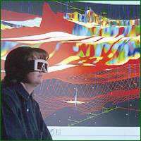
Computer Assisted
Exploration
One of the greatest
innovations in the history of petroleum exploration is the use of
computers to compile and assemble geologic data into a coherent 'map' of
the underground. Use of this computer technology is referred to as 'CAEX',
which is short for 'computer assisted exploration'.
 |
Geologist Using Interactive 3-D Seismic
|
|
Source: BP |
With the development of the
microprocessor, it has become relatively easy to use computers to assemble
seismic data that is collected from the field. This allows for the
processing of very large amounts of data, increasing the reliability and
informational content of the seismic model. There are three main types of
computer-assisted exploration models: two-dimensional (2-D),
three-dimensional (3-D), and most recently, four-dimensional (4-D). These
imaging techniques, while relying mainly on seismic data acquired in the
field, are becoming more and more sophisticated. Computer technology has
advanced so far that it is now possible to incorporate the data obtained
from different types of tests, such as logging, production information,
and gravimetric testing, which can all be combined to create a
'visualization' of the underground formation. Thus geologists and
geophysicists are able to combine all of their sources of data to compile
one clear, complete image of subsurface geology. An example of this is
shown where a geologist uses an interactive computer generated
visualization of 3-D seismic data to explore the subsurface layers.
3-D Seismic Imaging
| One of the biggest
breakthroughs in computer-aided exploration was the development of
three-dimensional (3-D) seismic imaging. Three-D imaging utilizes
seismic field data to generate a three dimensional 'picture' of
underground formations and geologic features. This, in essence,
allows the geophysicist and geologist to see a clear picture of the
composition of the Earth's crust in a particular area. This is
tremendously useful in allowing for the exploration of petroleum and
natural gas, as an actual image could be used to estimate the
probability of formations existing in a particular area, and the
characteristics of that potential formation. This technology has
been extremely successful in raising the success rate of exploration
efforts. In fact, using 3-D seismic has been estimated to increase
the likelihood of successful reservoir location by 50 percent. |
 |
|
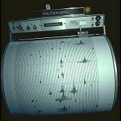
A
Seismograph |
|
Source: U.S. Geological Survey |
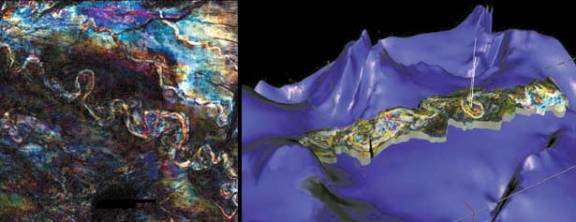 |
| An
Example of 3-D Seismic Imaging Technology |
|
Source: BP |
Although this technology is
very useful, it is also very costly. Three-D seismic imaging can cost
hundreds of thousands of dollars per square mile. The generation of 3-D
images requires data to be collected from several thousand locations, as
opposed to 2-D imaging, which only requires several hundred data points.
As such, 3-D imaging is a much more involved and prolonged process.
Therefore, it is usually used in conjunction with other exploration
techniques. For example, a geophysicist may use traditional 2-D modeling
and examination of geologic features to determine if there is a
probability of the presence of natural gas. Once these basic techniques
are used, 3-D seismic imaging may be used only in those areas that have a
high probability of containing reservoirs.
 |
|
Seismic Imaging in Practice |
|
Source: BP |
In addition to broadly
locating petroleum reservoirs, 3-D seismic imaging allows for the more
accurate placement of wells to be drilled. This increases the productivity
of successful wells, allowing for more petroleum and natural gas to be
extracted from the ground. In fact, 3-D seismic can increase the recovery
rates of productive wells to 40-50 percent, as opposed to 25-30 percent
with traditional 2-D exploration techniques.
In addition to broadly
locating petroleum reservoirs, 3-D seismic imaging allows for the more
accurate placement of wells to be drilled. This increases the productivity
of successful wells, allowing for more petroleum and natural gas to be
extracted from the ground. In fact, 3-D seismic can increase the recovery
rates of productive wells to 40 to 50 percent or greater, as opposed to 25
to 30 percent with traditional 2-D exploration techniques.
Three-D seismic imaging has
become an extremely important tool in the search natural gas. By 1980,
only 100 3-D seismic imaging tests had been performed. However, by the mid
1990s, 200 to 300 3-D seismic surveys were being performed each year. In
1996, in the Gulf of Mexico, one of the largest natural gas-producing
areas in the U.S., nearly 80 percent of wells drilled in the Gulf were
based on 3-D seismic data. In 1993, 75 percent of all onshore exploratory
surveys conducted used 3-D seismic imaging.
2-D Seismic Imaging
Two-dimensional (2-D)
computer-assisted exploration includes generating an image of subsurface
geology much in the same manner as in normal 2-D data interpretation.
However, with the aid of computer technology, it is possible to generate
more detailed maps more quickly than by the traditional method. In
addition, with 2-D CAEX it is possible to use color graphic displays
generated by a computer to highlight geologic features that may not be
apparent using traditional 2-D seismic imaging methods.
While 2-D seismic imaging
is less complicated and less detailed than 3-D imaging, it must be noted
that 3-D imaging techniques were developed prior to 2-D techniques. Thus,
although it does not appear to be the logical progression of techniques,
the simpler 2-D imaging techniques were actually an extension of 3-D
techniques, not the other way around. Because it is simpler, 2-D imaging
is much cheaper, and more easily and quickly performed, than 3-D imaging.
Because of this, 2-D CAEX imaging may be used in areas that are somewhat
likely to contain natural gas deposits, but not likely enough to justify
the full cost and time commitment required by 3-D imaging.
4-D Seismic Imaging
One of the latest
breakthroughs in seismic exploration and the modeling of underground rock
formations has been the introduction of four-dimensional (4-D) seismic
imaging. This type of imaging is an extension of 3-D imaging technology.
However, instead of achieving a simple, static image of the underground,
in 4-D imaging the changes in structures and properties of underground
formations are observed over time. Since the fourth dimension in 4-D
imaging is time, it is also referred to as 4-D 'time lapse' imaging.
 |
Geologists and Geophysicists:
Assembling Data |
|
Source: NGSA |
Various seismic readings of
a particular area are taken at different times, and this sequence of data
is fed into a powerful computer. The different images are amalgamated to
create a 'movie' of what is going on under the ground. By studying how
seismic images change over time, geologists can gain a better
understanding of many properties of the rock, including underground fluid
flow, viscosity, temperature and saturation. Although very important in
the exploration process, 4-D seismic images can also be used by petroleum
geologists to evaluate the properties of a reservoir, including how it is
expected to deplete once petroleum extraction has begun. Using 4-D imaging
on a reservoir can increase recovery rates above what can be achieved
using 2-D or 3-D imaging. Where the recovery rates using these two types
of images are 25 to 30 percent and 40 to 50 percent respectively, the use
of 4-D imaging can result in recovery rates of 65 to 70 percent.
Now that we have taken a look
at how natural gas deposits are found, the next step in the natural gas
line is the process of extraction.
Drilling Techniques
Horizontal Drilling
Horizontal drilling starts with a vertical well that turns horizontal
within the reservoir rock in order to expose more open hole to the
oil. These horizontal "legs" can be over a mile long; the longer the
exposure length, the more oil and natural gas is drained and the
faster it can flow. More oil and natural gas can be produced with
fewer wells and less surface disturbance. However, the technology only
can be employed in certain locations.
Multilateral Drilling
Sometimes oil and natural gas reserves are located in separate layers
underground. Multilateral drilling allows producers to branch out from
the main well to tap reserves at different depths. This dramatically
increases production from a single well and reduces the number of
wells drilled on the surface.
Extended Reach Drilling
Extended Reach Drilling allows producers to reach deposits that are
great distances away from the drilling rig. This can help producers
tap oil and natural gas deposits under surface areas where a vertical
well cannot be drilled, such as under developed or environmentally
sensitive areas. Wells can now reach out over 5 miles from the surface
location. Offshore, the use of extended reach drilling allows
producers to reach accumulations far from offshore platforms,
minimizing the number of platforms needed to produce all the oil and
gas. Onshore, dozens of wells can be drilled from a single location,
reducing surface impacts.
Complex Path Drilling
Complex Path Drilling creates well paths with have multiple twists and
turns to try to hit multiple accumulations from a single well
location. Using this technology can be more cost effective and produce
less waste and surface impacts than drilling multiple wells.
|
|
 |
|
Source: Duke Energy Gas Transmission Canada |
Natural gas, as it
is used by consumers, is much different from the natural
gas that is brought from underground up to the wellhead.
Although the processing of natural gas is in many
respects less complicated than the processing and
refining of crude oil, it is equally as necessary before
its use by end users.
The natural gas
used by consumers is composed almost entirely of
methane. However, natural gas found at the wellhead,
although still composed primarily of methane, is by no
means as pure. Raw natural gas comes from three types of
wells: oil wells, gas wells, and condensate wells.
Natural gas that comes from oil wells is typically
termed 'associated gas'. This gas can exist separate
from oil in the formation (free gas), or dissolved in
the crude oil (dissolved gas). Natural gas from gas and
condensate wells, in which there is little or no crude
oil, is termed 'nonassociated gas'. Gas wells typically
produce raw natural gas by itself, while condensate
wells produce free natural gas along with a semi-liquid
hydrocarbon condensate. Whatever the source of the
natural gas, once separated from crude oil (if present)
it commonly exists in mixtures with other hydrocarbons;
principally ethane, propane, butane, and pentanes. In
addition, raw natural gas contains water vapor, hydrogen
sulfide (H2S), carbon dioxide, helium,
nitrogen, and other compounds.
Natural gas
processing consists of separating all of the various
hydrocarbons and fluids from the pure natural gas, to
produce what is known as 'pipeline quality' dry natural
gas. Major transportation pipelines usually impose
restrictions on the make-up of the natural gas that is
allowed into the pipeline. That means that before the
natural gas can be transported it must be purified.
While the ethane, propane, butane, and pentanes must be
removed from natural gas, this does not mean that they
are all 'waste products'.
In fact,
associated hydrocarbons, known as 'natural gas liquids'
(NGLs) can be very valuable by-products of natural gas
processing. NGLs include ethane, propane, butane,
iso-butane, and natural gasoline. These NGLs are sold
separately and have a variety of different uses;
including enhancing oil recovery in oil wells, providing
raw materials for oil refineries or petrochemical
plants, and as sources of energy.
 |
|
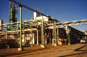
A Natural Gas Processing Plant |
|
Source: Duke Energy Gas Transmission Canada |
While some of the
needed processing can be accomplished at or near the
wellhead (field processing), the complete processing of
natural gas takes place at a processing plant, usually
located in a natural gas producing region. The extracted
natural gas is transported to these processing plants
through a network of gathering pipelines, which are
small-diameter, low pressure pipes. A complex gathering
system can consist of thousands of miles of pipes,
interconnecting the processing plant to upwards of 100
wells in the area. According to the American Gas
Association's Gas Facts 2000, there was an estimated
36,100 miles of gathering system pipelines in the U.S.
in 1999.
In addition to
processing done at the wellhead and at centralized
processing plants, some final processing is also
sometimes accomplished at 'straddle extraction plants'.
These plants are located on major pipeline systems.
Although the natural gas that arrives at these straddle
extraction plants is already of pipeline quality, in
certain instances there still exist small quantities of
NGLs, which are extracted at the straddle plants.
The actual
practice of processing natural gas to pipeline dry gas
quality levels can be quite complex, but usually
involves four main processes to remove the various
impurities:
- Oil and
Condensate Removal
- Water Removal
- Separation of
Natural Gas Liquids
- Sulfur and
Carbon Dioxide Removal
In addition to the
four processes above, heaters and scrubbers are
installed, usually at or near the wellhead. The
scrubbers serve primarily to remove sand and other
large-particle impurities. The heaters ensure that the
temperature of the gas does not drop too low. With
natural gas that contains even low quantities of water,
natural gas hydrates have a tendency to form when
temperatures drop. These hydrates are solid or
semi-solid compounds, resembling ice like crystals.
Should these hydrates accumulate, they can impede the
passage of natural gas through valves and gathering
systems. To reduce the occurrence of hydrates, small
natural gas-fired heating units are typically installed
along the gathering pipe wherever it is likely that
hydrates may form.
Oil and
Condensate Removal
In order to
process and transport associated dissolved natural gas,
it must be separated from the oil in which it is
dissolved. This separation of natural gas from oil is
most often done using equipment installed at or near the
wellhead.
The actual process
used to separate oil from natural gas, as well as the
equipment that is used, can vary widely. Although dry
pipeline quality natural gas is virtually identical
across different geographic areas, raw natural gas from
different regions may have different compositions and
separation requirements. In many instances, natural gas
is dissolved in oil underground primarily due to the
pressure that the formation is under. When this natural
gas and oil is produced, it is possible that it will
separate on its own, simply due to decreased pressure;
much like opening a can of soda pop allows the release
of dissolved carbon dioxide. In these cases, separation
of oil and gas is relatively easy, and the two
hydrocarbons are sent separate ways for further
processing. The most basic type of separator is known as
a conventional separator. It consists of a simple closed
tank, where the force of gravity serves to separate the
heavier liquids like oil, and the lighter gases, like
natural gas.
 |
|
Gas Processing Engineers |
|
Source: ChevronTexaco Corporation |
In certain
instances, however, specialized equipment is necessary
to separate oil and natural gas. An example of this type
of equipment is the Low-Temperature Separator (LTX).
This is most often used for wells producing high
pressure gas along with light crude oil or condensate.
These separators use pressure differentials to cool the
wet natural gas and separate the oil and condensate. Wet
gas enters the separator, being cooled slightly by a
heat exchanger. The gas then travels through a high
pressure liquid 'knockout', which serves to remove any
liquids into a low-temperature separator. The gas then
flows into this low-temperature separator through a
choke mechanism, which expands the gas as it enters the
separator. This rapid expansion of the gas allows for
the lowering of the temperature in the separator. After
liquid removal, the dry gas then travels back through
the heat exchanger and is warmed by the incoming wet
gas. By varying the pressure of the gas in various
sections of the separator, it is possible to vary the
temperature, which causes the oil and some water to be
condensed out of the wet gas stream. This basic
pressure-temperature relationship can work in reverse as
well, to extract gas from a liquid oil stream.
Water Removal
In addition to
separating oil and some condensate from the wet gas
stream, it is necessary to remove most of the associated
water. Most of the liquid, free water associated with
extracted natural gas is removed by simple separation
methods at or near the wellhead. However, the removal of
the water vapor that exists in solution in natural gas
requires a more complex treatment. This treatment
consists of 'dehydrating' the natural gas, which usually
involves one of two processes: either absorption, or
adsorption.
Absorption occurs
when the water vapor is taken out by a dehydrating
agent. Adsorption occurs when the water vapor is
condensed and collected on the surface.
Glycol
Dehydration
An example of
absorption dehydration is known as Glycol Dehydration.
In this process, a liquid desiccant dehydrator serves to
absorb water vapor from the gas stream. Glycol, the
principal agent in this process, has a chemical affinity
for water. This means that, when in contact with a
stream of natural gas that contains water, glycol will
serve to 'steal' the water out of the gas stream.
Essentially, glycol dehydration involves using a glycol
solution, usually either diethylene glycol (DEG) or
triethylene glycol (TEG), which is brought into contact
with the wet gas stream in what is called the
'contactor'. The glycol solution will absorb water from
the wet gas. Once absorbed, the glycol particles become
heavier and sink to the bottom of the contactor where
they are removed. The natural gas, having been stripped
of most of its water content, is then transported out of
the dehydrator. The glycol solution, bearing all of the
water stripped from the natural gas, is put through a
specialized boiler designed to vaporize only the water
out of the solution. While water has a boiling point of
212 degrees Fahrenheit, glycol does not boil until 400
degrees Fahrenheit. This boiling point differential
makes it relatively easy to remove water from the glycol
solution, allowing it be reused in the dehydration
process.
A new innovation
in this process has been the addition of flash tank
separator-condensers. As well as absorbing water from
the wet gas stream, the glycol solution occasionally
carries with it small amounts of methane and other
compounds found in the wet gas. In the past, this
methane was simply vented out of the boiler. In addition
to losing a portion of the natural gas that was
extracted, this venting contributes to air pollution and
the greenhouse effect. In order to decrease the amount
of methane and other compounds that are lost, flash tank
separator-condensers work to remove these compounds
before the glycol solution reaches the boiler.
Essentially, a flash tank separator consists of a device
that reduces the pressure of the glycol solution stream,
allowing the methane and other hydrocarbons to vaporize
('flash'). The glycol solution then travels to the
boiler, which may also be fitted with air or water
cooled condensers, which serve to capture any remaining
organic compounds that may remain in the glycol
solution. In practice, according to the Department of
Energy's Office of Fossil Energy, these systems have
been shown to recover 90 to 99 percent of methane that
would otherwise be flared into the atmosphere.
Solid-Desiccant
Dehydration
Solid-desiccant
dehydration is the primary form of dehydrating natural
gas using adsorption, and usually consists of two or
more adsorption towers, which are filled with a solid
desiccant. Typical desiccants include activated alumina
or a granular silica gel material. Wet natural gas is
passed through these towers, from top to bottom. As the
wet gas passes around the particles of desiccant
material, water is retained on the surface of these
desiccant particles. Passing through the entire
desiccant bed, almost all of the water is adsorbed onto
the desiccant material, leaving the dry gas to exit the
bottom of the tower.
 |
|
Absorption Towers |
|
Source: Duke Energy Gas Transmission Canada |
Solid-desiccant
dehydrators are typically more effective than glycol
dehydrators, and are usually installed as a type of
straddle system along natural gas pipelines. These types
of dehydration systems are best suited for large volumes
of gas under very high pressure, and are thus usually
located on a pipeline downstream of a compressor
station. Two or more towers are required due to the fact
that after a certain period of use, the desiccant in a
particular tower becomes saturated with water. To
'regenerate' the desiccant, a high-temperature heater is
used to heat gas to a very high temperature. Passing
this heated gas through a saturated desiccant bed
vaporizes the water in the desiccant tower, leaving it
dry and allowing for further natural gas dehydration.
|
Separation of Natural Gas Liquids
Natural
gas coming directly from a well contains many
natural gas liquids that are commonly removed.
In most instances, natural gas liquids (NGLs)
have a higher value as separate products, and it
is thus economical to remove them from the gas
stream. The removal of natural gas liquids
usually takes place in a relatively centralized
processing plant, and uses techniques similar to
those used to dehydrate natural gas.
There are
two basic steps to the treatment of natural gas
liquids in the natural gas stream. First, the
liquids must be extracted from the natural gas.
Second, these natural gas liquids must be
separated themselves, down to their base
components. |
 |
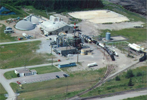
|
Gas Processing Plant with Absorption
Towers |
|
Source: Duke Energy Gas Transmission
Canada |
|
NGL Extraction
There are two
principle techniques for removing NGLs from the natural
gas stream: the absorption method and the cryogenic
expander process. According to the Gas Processors
Association, these two processes account for around 90
percent of total natural gas liquids production.
The Absorption
Method
 |
|
Pipes and Absorption Towers |
|
Source: Duke Energy Gas Transmission Canada |
The absorption
method of NGL extraction is very similar to using
absorption for dehydration. The main difference is that,
in NGL absorption, an absorbing oil is used as opposed
to glycol. This absorbing oil has an 'affinity' for NGLs
in much the same manner as glycol has an affinity for
water. Before the oil has picked up any NGLs, it is
termed 'lean' absorption oil. As the natural gas is
passed through an absorption tower, it is brought into
contact with the absorption oil which soaks up a high
proportion of the NGLs. The 'rich' absorption oil, now
containing NGLs, exits the absorption tower through the
bottom. It is now a mixture of absorption oil, propane,
butanes, pentanes, and other heavier hydrocarbons. The
rich oil is fed into lean oil stills, where the mixture
is heated to a temperature above the boiling point of
the NGLs, but below that of the oil. This process allows
for the recovery of around 75 percent of butanes, and 85
- 90 percent of pentanes and heavier molecules from the
natural gas stream.
The basic
absorption process above can be modified to improve its
effectiveness, or to target the extraction of specific
NGLs. In the refrigerated oil absorption method, where
the lean oil is cooled through refrigeration, propane
recovery can be upwards of 90 percent, and around 40
percent of ethane can be extracted from the natural gas
stream. Extraction of the other, heavier NGLs can be
close to 100 percent using this process.
The Cryogenic
Expansion Process
Cryogenic
processes are also used to extract NGLs from natural
gas. While absorption methods can extract almost all of
the heavier NGLs, the lighter hydrocarbons, such as
ethane, are often more difficult to recover from the
natural gas stream. In certain instances, it is economic
to simply leave the lighter NGLs in the natural gas
stream. However, if it is economic to extract ethane and
other lighter hydrocarbons, cryogenic processes are
required for high recovery rates. Essentially, cryogenic
processes consist of dropping the temperature of the gas
stream to around -120 degrees Fahrenheit.
There are a number
of different ways of chilling the gas to these
temperatures, but one of the most effective is known as
the turbo expander process. In this process, external
refrigerants are used to cool the natural gas stream.
Then, an expansion turbine is used to rapidly expand the
chilled gases, which causes the temperature to drop
significantly. This rapid temperature drop condenses
ethane and other hydrocarbons in the gas stream, while
maintaining methane in gaseous form. This process allows
for the recovery of about 90 to 95 percent of the ethane
originally in the gas stream. In addition, the expansion
turbine is able to convert some of the energy released
when the natural gas stream is expanded into
recompressing the gaseous methane effluent, thus saving
energy costs associated with extracting ethane.
The extraction of
NGLs from the natural gas stream produces both cleaner,
purer natural gas, as well as the valuable hydrocarbons
that are the NGLs themselves.
Natural Gas
Liquid Fractionation
Once NGLs have
been removed from the natural gas stream, they must be
broken down into their base components to be useful.
That is, the mixed stream of different NGLs must be
separated out. The process used to accomplish this task
is called fractionation. Fractionation works based on
the different boiling points of the different
hydrocarbons in the NGL stream. Essentially,
fractionation occurs in stages consisting of the boiling
off of hydrocarbons one by one. The name of a particular
fractionator gives an idea as to its purpose, as it is
conventionally named for the hydrocarbon that is boiled
off. The entire fractionation process is broken down
into steps, starting with the removal of the lighter
NGLs from the stream. The particular fractionators are
used in the following order:
- Deethanizer
- this step separates the ethane from the NGL
stream.
- Depropanizer
- the next step separates the propane.
- Debutanizer
- this step boils off the butanes, leaving the
pentanes and heavier hydrocarbons in the NGL stream.
- Butane
Splitter or Deisobutanizer - this step separates
the iso and normal butanes.
By proceeding from
the lightest hydrocarbons to the heaviest, it is
possible to separate the different NGLs reasonably
easily.
Sulfur and
Carbon Dioxide Removal
In addition to
water, oil, and NGL removal, one of the most important
parts of gas processing involves the removal of sulfur
and carbon dioxide. Natural gas from some wells contains
significant amounts of sulfur and carbon dioxide. This
natural gas, because of the rotten smell provided by its
sulfur content, is commonly called 'sour gas'. Sour gas
is undesirable because the sulfur compounds it contains
can be extremely harmful, even lethal, to breathe. Sour
gas can also be extremely corrosive. In addition, the
sulfur that exists in the natural gas stream can be
extracted and marketed on its own. In fact, according to
the USGS, U.S. sulfur production from gas processing
plants accounts for about 15 percent of the total U.S.
production of sulfur.
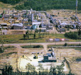
 |
|
Gas Sweetening Plant |
|
Source: Duke Energy Gas Transmission Canada |
Sulfur exists in
natural gas as hydrogen sulfide (H2S), and
the gas is usually considered sour if the hydrogen
sulfide content exceeds 5.7 milligrams of H2S
per cubic meter of natural gas. The process for removing
hydrogen sulfide from sour gas is commonly referred to
as 'sweetening' the gas.
The primary
process for sweetening sour natural gas is quite similar
to the processes of glycol dehydration and NGL
absorption. In this case, however, amine solutions are
used to remove the hydrogen sulfide. This process is
known simply as the 'amine process', or alternatively as
the Girdler process, and is used in 95 percent of U.S.
gas sweetening operations. The sour gas is run through a
tower, which contains the amine solution. This solution
has an affinity for sulfur, and absorbs it much like
glycol absorbing water. There are two principle amine
solutions used, monoethanolamine (MEA) and
diethanolamine (DEA). Either of these compounds, in
liquid form, will absorb sulfur compounds from natural
gas as it passes through. The effluent gas is virtually
free of sulfur compounds, and thus loses its sour gas
status. Like the process for NGL extraction and glycol
dehydration, the amine solution used can be regenerated
(that is, the absorbed sulfur is removed), allowing it
to be reused to treat more sour gas.
Although most sour
gas sweetening involves the amine absorption process, it
is also possible to use solid desiccants like iron
sponges to remove the sulfide and carbon dioxide.
Sulfur can be sold
and used if reduced to its elemental form. Elemental
sulfur is a bright yellow powder like material, and can
often be seen in large piles near gas treatment plants,
as is shown. In order to recover elemental sulfur from
the gas processing plant, the sulfur containing
discharge from a gas sweetening process must be further
treated. The process used to recover sulfur is known as
the Claus process, and involves using thermal and
catalytic reactions to extract the elemental sulfur from
the hydrogen sulfide solution.
 |
|
Elemental Sulfur Production in a Gas Treatment
Plant |
|
Source: Duke Energy Gas Transmission Canada |
In all, the Claus
process is usually able to recover 97 percent of the
sulfur that has been removed from the natural gas
stream. Since it is such a polluting and harmful
substance, further filtering, incineration, and 'tail
gas' clean up efforts ensure that well over 98 percent
of the sulfur is recovered.
Gas processing is
an instrumental piece of the natural gas value chain. It
is instrumental in ensuring that the natural gas
intended for use is as clean and pure as possible,
making it the clean burning and environmentally sound
energy choice. Once the natural gas has been fully
processed, and is ready to be consumed, it must be
transported from those areas that produce natural gas,
to those areas that require it.
|
|
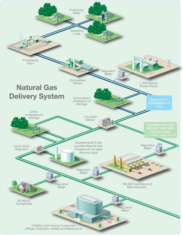
Natural gas is moved
by pipelines from the producing fields to consumers. Since natural gas demand is
greater in the winter, gas is stored along the way in large underground storage
systems, such as old oil and gas wells or caverns formed in old salt beds. The
gas remains there until it is added back into the pipeline when people begin to
use more gas, such as in the winter to heat homes. When chilled to very cold
temperatures, approximately -260 degrees Fahrenheit, natural gas changes into a
liquid and can be stored in this form. Liquefied natural gas (LNG) can be loaded
onto tankers (large ships with several domed tanks) and moved across the ocean
to deliver gas to other countries. Once in this form, it takes up only 1/600th
of the space that it would in its gaseous state. When this LNG is received in
the United States, it can be shipped by truck to be held in large chilled tanks
close to users or turned back into gas to add to pipelines.
Natural gas -
proved reserves


Credit:BP, Energy
Information Administration, U.S. Department of Energy, CIA, American Gas
Association, Association of Oil Pipe Lines
|